How to Make a N Cable Using Solder and Crimp Connectors
Summary
N-type cables consist of a coaxial cable fitted with N-type connectors, commonly used with a wide range of radio communication equipment, primarily in the UHF band.
While several methods exist for attaching these connectors, the most prevalent are soldering and clamping, and a combination of soldering and crimping.
This guide will focus on the latter, providing a step-by-step walkthrough of how to assemble an N-type cable using soldering and crimping techniques.
Below are the step-by-step instructions for attaching a N connector:
1. Solder the cable’s inner conductor (core) to the center contact of the connector.
2. Place the connector body over the cable’s outer jacket and firmly crimp the crimp sleeve in place.

Benefits of Soldering and Crimping N Connectors
Lightweight and Affordable Connectors
After purchasing a crimping tool, you can keep costs low.
Work Procedure
Instructions for fabricating a solder and crimp type N cable are provided below.
The steps may vary depending on the product, but NP-58A is used as a representative example.
Cable mounting diagrams can be downloaded from the website for all products.
Please refer to “View Datasheet” on the product details page.

Cut the cable
Strip the cable
Solder the center contact
Crimp the connector body
Conduct continuity and insulation resistance checks
Cut the cable
Cut the cable to the specified length. The key point to pay attention to here is the “cut length.”
Even if the total length of the cable is the same, the “cut length” required will vary depending on the reference point for the overall length and the internal dimensions of the connector.
When the total cable length is short, or when the cable is used for measurement applications, precise cut lengths are especially important.
・ If the total length is specified from the tip of the connector: The cut length will be shorter than the total length.
・ If the total length is specified from the base of the connector: The cut length will be longer than the total length.
Trivia: Automatic Cable Cutting Machines

Although cable cutting is often performed manually using cutters, it can also be done with an automatic cable cutting machine.
At Tyclon, we use the “MultiStrip 9480” by Schleuniger, which allows us to cut cables quickly and accurately.
This machine is also capable of performing the subsequent “cable stripping” process automatically.
Strip the cable
Pass the crimp sleeve onto the cable, then cut the insulator, outer conductor (braid), and outer jacket (sheath) according to the cable preparation diagram.
When stripping the cable, make sure to follow the dimensions specified in the installation manual. If using a cutter, you may mark the cut points with a marker.
Trivia: Cable Stripping Devices

Cable stripping is often done using a cutter or similar tool. On job sites, portable and simple strippers are also highly valued for their convenience.
At Tyclon, we use the "Coax Strip 5300" and "Coax Strip 5500" from Schleuniger.
By registering the strip dimensions, we can repeatedly cut cables to the same exact size, ensuring quick and precise cable stripping every time.
Solder the center contact
Attach the center contact to the inner conductor (core wire) and solder it in place.
Be careful to ensure that the solder does not bulge up and that there are no gaps between the center contact and the insulator.
Soldering requires skill, as defects known as "cold solder joints" ("imo soldering" in Japanese) can occur due to excessive solder, overly high temperatures, or low temperatures. These defects include trapped air causing expansion, or rough surfaces caused by evaporation.
At Tyclon, we conduct an internal “soldering test,” and experienced technicians carry out careful soldering work.
After soldering, the contact is pulled using radio pliers (to about 1 kg of force) to confirm that there are no issues.
In addition, we use dedicated jigs to hold the parts in place, ensuring precise and stable soldering.
Trivia: Pre-Soldering (Tinning)
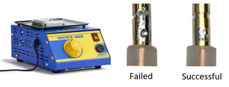
At Tyclon, we sometimes perform pre-soldering (tinning) on the inner conductor (core wire) before soldering the center contact.
Although this is not an essential step, for thick cables or cables with stranded inner conductors, soldering only at the contact may result in a weak connection.
By pre-soldering (tinning) the wire, it becomes easier for the solder to bond, resulting in a stronger and more reliable connection.
We use HAKKO's solder pot “FX-300” to thoroughly tin the inner conductor by soaking it in solder.
Trivia: Lead-Free

At Tyclon, we use lead-free solder for all cable assemblies.
While our standard connectors do contain lead, the RoHS directive allows up to 40,000 ppm of lead content as an exemption.
However, environmental regulations on lead, which is harmful to both humans and the environment, are expanding and strengthening globally, originating from Europe.
For this reason, Tyclon has developed "lead-free connectors" using Mitsubishi Materials' GloBrass®—a lead-free, free-cutting brass.
These lead-free connectors are now available as custom-order products.
For more details, please see our page on Lead Free Connectors.
Crimp the connector body
Attach the shell so that it fits between the insulator and the outer conductor (braid) of the coaxial cable.
When the center contact is properly seated, you will hear a clicking sound.
Slide the crimp sleeve over the outer conductor, then crimp it using section A of the crimping tool.
The crimp height at the measurement position should be 6.10 to 6.13 mm. As previously mentioned, please adjust the strength adjustment dial so that it fits within the specified crimp height range.
Be careful not to let the frame or screw part of the crimping tool come into contact with the connector.
Trivia: Using a Crimping Jig
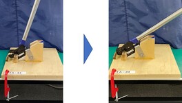
A significant amount of force is required to crimp the sleeve onto the connector body. At Tyclon, we have developed a dedicated jig for use with the crimping tool, which helps improve both work efficiency and accuracy.
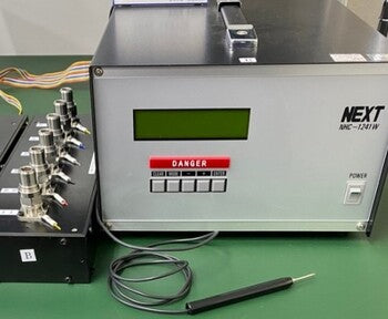
Perform continuity and insulation resistance checks
All Tyclon cable assemblies undergo continuity and insulation resistance testing with a tester after completion.
This process helps detect issues such as internal wire breaks or soldering mistakes that cannot be identified through visual inspection.
Only products that have passed other in-house inspection criteria are shipped.
FAQs
QIs custom cable assembly available?
QIs custom cable assembly available?
Yes, we can manufacture custom cables according to your requirements. Please let us know your specifications or needs via the inquiry form.
QDo you offer lead-free connectors?
QDo you offer lead-free connectors?
Yes, we provide lead-free connectors made with GloBrass® (lead-free free-cutting brass) from Mitsubishi Materials. For more details, please refer to the Lead Free Connectors page.
View More
QWhat is your product inspection process?
QWhat is your product inspection process?
All finished products undergo 100% continuity and insulation resistance testing. Only products that have passed all in-house inspection criteria are shipped.
QCan you tighten fasteners to a specified torque?
QCan you tighten fasteners to a specified torque?
Yes, we can accommodate specific torque requirements. Please specify this in your order if needed.
QCan you handle large-volume orders?
QCan you handle large-volume orders?
Yes, we can handle large-volume orders. Please contact us to discuss lead times.
Q Is it possible to request product samples?
Q Is it possible to request product samples?
Sample availability depends on the specific case. Please contact us via the inquiry form for details.