RF Coaxial Cable Specifications, Standards, and Selection Guide
What Are RF Coaxial Cables
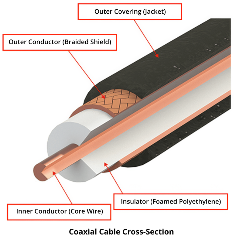
RF Coaxial cables, often called RF cables, are essential in telecommunications for efficiently transmitting radio frequency (RF) signals. Their design prioritizes minimal signal loss and reflection between the transmitter and receiver, featuring unbalanced connections, effective shielding against electromagnetic wave leakage, and a degree of flexibility. Many are manufactured to meet rigorous standards, such as MIL (military) specifications.
This page is dedicated to exploring the different types and standards of coaxial cables and includes a detailed list to help you identify the right cable for your application. If you're looking for a broader understanding of coaxial cable fundamentals, including their detailed structure, general uses, and core features, please see our main guide:
Types and Standards of RF Coaxial Cables
RG standards
U.S. military MIL-standard cables begin with “RG” (Radio Guide) and are also known as mil-spec cables.
Example: RG-58A/U (commonly used general-purpose cable)
- - RG: Radio Guide (an abbreviation for radio frequency coaxial cable, general purpose)
- - 58: Type number (assigned sequentially, not by thickness as in the JIS standard)
- - A: Assignment code (alphabetical, such as A to C, indicating standard revisions)
- - U: Universal (for general use)
RG-58A/U features a solid inner conductor, while RG-58C/U uses a stranded inner conductor. Note that differences based on the type number can vary by product.
Common examples include RG58, RG174, and RG316, each differing in diameter, impedance, and application. These are widely used in RF systems depending on frequency range and installation requirements.
Cable types
In addition to RG standards, RF coaxial cables can also be classified based on their structure and application.
These classifications differ from RG standards, which define cable specifications, while the following types focus on structure and application.
- Flexible coaxial cables: General-purpose cables with good flexibility (e.g., RG58).
- Semi-rigid coaxial cables: Rigid outer conductor for stable high-frequency performance. Commonly used in RF modules and test equipment.
- Semi-flexible coaxial cables: A balance between flexibility and performance.
- Low-loss coaxial cables: Designed to minimize signal attenuation over long distances.
- High-frequency coaxial cables: Optimized for GHz-level signal transmission.
- Micro coaxial cables: Ultra-thin cables used in compact electronic devices.
How to Choose RF Coaxial Cables
RF coaxial cables are generally selected in this order: the connector type is usually chosen first based on the transmitter, receiver, antenna, or similar, and then the cable is selected.
Impedance
Select impedance based on equipment: 50 Ohm for radio power transmission and 75 Ohm for video or audio signals, matching the transmitter, receiver, or antenna.
Frequency Band
Cables and connectors support specific frequency ranges. For frequencies above 18 GHz, specialized cables designed for high-frequency performance are required.
Cable Thickness
Cable thickness affects fit in wiring spaces. Thicker cables are typical for external use, while thinner cables are preferred for internal equipment wiring.
Total Cable Length
Longer cable lengths increase signal loss. For external wiring, thicker cables with lower loss are selected to maintain signal integrity over distance.
Cable Stiffness
Thicker cables tend to be stiffer and less flexible. Based on installation requirements, choose cables with an appropriate bending radius and flexibility.
Other Considerations
Environmental factors like waterproofing, high temperature, and humidity must be considered to ensure reliable cable performance in the operating environment.
Trivia: Bending Radius
Coaxial cable is flexible but must not be bent beyond its minimum bend radius. Bending too tightly can affect signal transmission. This radius, often called R, is usually 10 times the cable’s outer diameter. Exceeding it can cause signal loss or damage.
RF Coaxial Cable Specifications
RF Coaxial Cable Types
This list shows RF coaxial cables with their impedance, construction, materials, and diameters. Values are typical and may vary by manufacturer. Abbreviations for construction and materials are explained below.
RG-5/U
Impedance: 52.5 Ohm
Inner Conductor (Number of Strands / Wire Diameter): 1 / 1.295 mm
Inner Conductor (Configuration): AC
Insulator (Diameter): 4.7 mm
Insulator (Material): PE
Outer Conductor (Diameter): 6.3 mm
Outer Conductor (Configuration): AA
Outer Sheath (Diameter): 8.4 mm
Outer Sheath (Material): PVC
RG-8/U
Impedance: 52 Ohm
Inner Conductor (Number of Strands / Wire Diameter): 7 / 0.724 mm
Inner Conductor (Configuration): AC
Insulator (Diameter): 7.2 mm
Insulator (Material): PE
Outer Conductor (Diameter): 8.1 mm
Outer Conductor (Configuration): A
Outer Sheath (Diameter): 10.3 mm
Outer Sheath (Material): PVC
Find compatible connectors for RG-8/U →
RG-9/U
Impedance: 51 Ohm
Inner Conductor (Number of Strands / Wire Diameter): 7 / 0.724 mm
Inner Conductor (Configuration): S
Insulator (Diameter): 7.1 mm
Insulator (Material): PE
Outer Conductor (Diameter): 8.7 mm
Outer Conductor (Configuration): SA
Outer Sheath (Diameter): 10.7 mm
Outer Sheath (Material): PVC
RG-10/U
Impedance: 52 Ohm
Inner Conductor (Number of Strands / Wire Diameter): 7 / 0.724 mm
Inner Conductor (Configuration): AC
Insulator (Diameter): 7.2 mm
Insulator (Material): PE
Outer Conductor (Diameter): 8.1 mm
Outer Conductor (Configuration): A
Outer Sheath (Diameter): 10.3 mm
Outer Sheath (Material): PVC*
*RG-10/U has an additional braided outer covering (finished O.D. 12.0 mm) over the outer sheath.
Find compatible connectors for RG-10/U →
RG-11/U
Impedance: 75 Ohm
Inner Conductor (Number of Strands / Wire Diameter): 7 / 0.404 mm
Inner Conductor (Configuration): T
Insulator (Diameter): 7.2 mm
Insulator (Material): PE
Outer Conductor (Diameter): 8.1 mm
Outer Conductor (Configuration): A
Outer Sheath (Diameter): 10.3 mm
Outer Sheath (Material): PVC
Find compatible connectors for RG-11/U →
RG-14/U
Impedance: 52 Ohm
Inner Conductor (Number of Strands / Wire Diameter): 1 / 2.591 mm
Inner Conductor (Configuration): AC
Insulator (Diameter): 9.4 mm
Insulator (Material): PE
Outer Conductor (Diameter): 11.2 mm
Outer Conductor (Configuration): AA
Outer Sheath (Diameter): 13.8 mm
Outer Sheath (Material): PVC
Find compatible connectors for RG-14/U →
RG-17/U
Impedance: 52 Ohm
Inner Conductor (Number of Strands / Wire Diameter): 1 / 4.775 mm
Inner Conductor (Configuration): AC
Insulator (Diameter): 17.3 mm
Insulator (Material): PE
Outer Conductor (Diameter): 18.6 mm
Outer Conductor (Configuration): A
Outer Sheath (Diameter): 22.1 mm
Outer Sheath (Material): PVC
Find compatible connectors for RG-17/U →
RG-55/U
Impedance: 53.5 Ohm
Inner Conductor (Number of Strands / Wire Diameter): 1 / 0.813 mm
Inner Conductor (Configuration): AC
Insulator (Diameter): 2.9 mm
Insulator (Material): PE
Outer Conductor (Diameter): 4.2 mm
Outer Conductor (Configuration): TT
Outer Sheath (Diameter): 5.0 mm
Outer Sheath (Material): PE
Find compatible connectors for RG-55/U →
RG-58/U
Impedance: 53.5 Ohm
Inner Conductor (Number of Strands / Wire Diameter): 1 / 0.813 mm
Inner Conductor (Configuration): AC
Insulator (Diameter): 2.9 mm
Insulator (Material): PE
Outer Conductor (Diameter): 3.6 mm
Outer Conductor (Configuration): T
Outer Sheath (Diameter): 5.0 mm
Outer Sheath (Material): PVC
Find compatible connectors for RG-58/U →
RG-58A/U
Impedance: 50 Ohm
Inner Conductor (Number of Strands / Wire Diameter): 19 / 0.180 mm
Inner Conductor (Configuration): T
Insulator (Diameter): 2.9 mm
Insulator (Material): PE
Outer Conductor (Diameter): 3.6 mm
Outer Conductor (Configuration): T
Outer Sheath (Diameter): 5.0 mm
Outer Sheath (Material): PVC
Find compatible connectors for RG-58A/U →
RG-59/U
Impedance: 75 Ohm
Inner Conductor (Number of Strands / Wire Diameter): 1 / 0.643 mm
Inner Conductor (Configuration): CW
Insulator (Diameter): 3.7 mm
Insulator (Material): PE
Outer Conductor (Diameter): 4.5 mm
Outer Conductor (Configuration): A
Outer Sheath (Diameter): 6.2 mm
Outer Sheath (Material): PVC
Find compatible connectors for RG-59/U →
RG-62/U
Impedance: 93 Ohm
Inner Conductor (Number of Strands / Wire Diameter): 1 / 0.643 mm
Inner Conductor (Configuration): CW
Insulator (Diameter): 3.7 mm
Insulator (Material): SSt
Outer Conductor (Diameter): 4.5 mm
Outer Conductor (Configuration): A
Outer Sheath (Diameter): 6.2 mm
Outer Sheath (Material): PVC
Find compatible connectors for RG-62/U →
RG-62A/U
Impedance: 93 Ohm
Inner Conductor (Number of Strands / Wire Diameter): 1 / 0.643 mm
Inner Conductor (Configuration): CW
Insulator (Diameter): 3.7 mm
Insulator (Material): SSt
Outer Conductor (Diameter): 4.5 mm
Outer Conductor (Configuration): A
Outer Sheath (Diameter): 6.2 mm
Outer Sheath (Material): PVC
Find compatible connectors for RG-62A/U →
RG-71/U
Impedance: 93 Ohm
Inner Conductor (Number of Strands / Wire Diameter): 1 / 0.643 mm
Inner Conductor (Configuration): CW
Insulator (Diameter): 3.7 mm
Insulator (Material): SSt
Outer Conductor (Diameter): 5.0 mm
Outer Conductor (Configuration): TT
Outer Sheath (Diameter): 5.8 mm
Outer Sheath (Material): PE
RG-142B/U
Impedance: 50 Ohm
Inner Conductor (Number of Strands / Wire Diameter): 1 / 0.991 mm
Inner Conductor (Configuration): SCW
Insulator (Diameter): 2.9 mm
Insulator (Material): TFE
Outer Conductor (Diameter): 4.2 mm
Outer Conductor (Configuration): SS
Outer Sheath (Diameter): 5.2 mm
Outer Sheath (Material): FEP
Find compatible connectors for RG-142B/U →
RG-174/U
Impedance: 50 Ohm
Inner Conductor (Number of Strands / Wire Diameter): 7 / 0.160 mm
Inner Conductor (Configuration): CW
Insulator (Diameter): 1.5 mm
Insulator (Material): PE
Outer Conductor (Diameter): 2.0 mm
Outer Conductor (Configuration): T
Outer Sheath (Diameter): 2.5 mm
Outer Sheath (Material): PVC
Find compatible connectors for RG-174/U →
RG-178B/U
Impedance: 50 Ohm
Inner Conductor (Number of Strands / Wire Diameter): 7 / 0.102 mm
Inner Conductor (Configuration): SCW
Insulator (Diameter): 0.86 mm
Insulator (Material): TFE
Outer Conductor (Diameter): 1.0 mm
Outer Conductor (Configuration): S
Outer Sheath (Diameter): 1.8 mm
Outer Sheath (Material): FEP
RG-187A/U
Impedance: 75 Ohm
Inner Conductor (Number of Strands / Wire Diameter): 7 / 0.102 mm
Inner Conductor (Configuration): SCW
Insulator (Diameter): 1.5 mm
Insulator (Material): TFE
Outer Conductor (Diameter): 2.0 mm
Outer Conductor (Configuration): S
Outer Sheath (Diameter): 2.7 mm
Outer Sheath (Material): TFE
Find compatible connectors for RG-187A/U →
RG-188A/U
Impedance: 50 Ohm
Inner Conductor (Number of Strands / Wire Diameter): 7 / 0.170 mm
Inner Conductor (Configuration): SCW
Insulator (Diameter): 1.5 mm
Insulator (Material): TFE
Outer Conductor (Diameter): 2.0 mm
Outer Conductor (Configuration): S
Outer Sheath (Diameter): 2.6 mm
Outer Sheath (Material): TFE
Find compatible connectors for RG-188A/U →
RG-196A/U
Impedance: 50 Ohm
Inner Conductor (Number of Strands / Wire Diameter): 7 / 0.102 mm
Inner Conductor (Configuration): SCW
Insulator (Diameter): 0.86 mm
Insulator (Material): TFE
Outer Conductor (Diameter): 1.3 mm
Outer Conductor (Configuration): S
Outer Sheath (Diameter): 2.0 mm
Outer Sheath (Material): TFE
RG-223/U
Impedance: 50 Ohm
Inner Conductor (Number of Strands / Wire Diameter): 1 / 0.889 mm
Inner Conductor (Configuration): S
Insulator (Diameter): 2.9 mm
Insulator (Material): PE
Outer Conductor (Diameter): 4.2 mm
Outer Conductor (Configuration): SS
Outer Sheath (Diameter): 5.3 mm
Outer Sheath (Material): PVC
Find compatible connectors for RG-223/U →
RG-316/U
Impedance: 50 Ohm
Inner Conductor (Number of Strands / Wire Diameter): 7 / 0.170 mm
Inner Conductor (Configuration): SCW
Insulator (Diameter): 1.5 mm
Insulator (Material): TFE
Outer Conductor (Diameter): 2.0 mm
Outer Conductor (Configuration): S
Outer Sheath (Diameter): 2.4 mm
Outer Sheath (Material): FEP
Find compatible connectors for RG-316/U →
Temperature Range by Sheath Material
The operating temperature range of RF coaxial cables is mainly determined by the outer sheath material and can also be influenced by the insulation material. The temperature range for each material is as follows.
PVC
Vinyl Chloride
−15 to 60 °C
PE
Polyethylene
−40 to 75 °C
TFE
Tetrafluorocarbon Resin (Teflon)
−70 to 250 °C
FEP
4-6 Fluorinated Ethylene-Propylene Copolymer
−70 to 200 °C
RF Coaxial Cable Construction and Material Abbreviations
The names of construction types and materials, indicated by abbreviations in the list of RF coaxial cables above, are shown below.
Inner Conductor Materials
AC
Copper alloy with traces of silver, lead, or tin
T
Tinned soft copper wire
S
Silver-plated soft copper wire
CW
Copper-coated steel wire
SCW
Silver-plated copper-clad steel wire
Insulator Materials
PE
Enhanced polyethylene
SST
Polyethylene cordel + polyethylene pipe
TFE
Tetrafluorocarbon resin (Teflon)
Outer Conductor Materials
A
Single-layer bare copper wire braid
AA
Double-layer bare copper wire braid
T
Single-layer tin-plated copper wire braid
TT
Double-layer tin-plated copper wire braid
S
Single-layer silver-plated copper wire braid
SS
Double-layer silver-plated copper wire braid
SA
Single-layer silver-plated copper wire braid + single-layer bare copper wire braid
Outer Sheath Materials
PVC
Polyvinyl chloride (PVC)
PE
Polyethylene
TFE
Polytetrafluoroethylene (PTFE / Teflon)
FEP
Ethylene tetrafluoroethylene-hexafluoropropylene copolymer (ETFE-HFP copolymer)
Key Differences at a Glance
- Impedance:
50Ohm (RG-58, RG-316) → RF applications
75Ohm (RG-6) → Video / broadcast
- Size:
RG-316 < RG-58 < RG-6
- Flexibility:
RG-316 > RG-58 > RG-6
- Typical Use:
RG-58 → General RF
RG-316 → Compact / flexible applications
RG-6 → TV and video signals
RF Coaxial Cable Types FAQs
QWhat types of coaxial cables are there?
QWhat types of coaxial cables are there?
Coaxial cables are primarily categorized under two standards: the Japanese Industrial Standards (JIS) used in Japan, such as 5C-2V, 3D-2V, and 5D-FB, and the U.S. military standard known as Radio Guide (RG) cables, including RG-58, RG-174, and RG-316. Selecting the right standard depends on your specific application requirements.
QWhat types of impedance are there for coaxial cables?
QWhat types of impedance are there for coaxial cables?
Coaxial cables generally come in two impedance types: 50 ohms and 75 ohms. The 50-ohm cables are typically used in radio communications and high-frequency circuits, while 75-ohm cables are preferred for television broadcasting and video transmission systems, based on their electrical performance suited to each application.
QHow is the thickness of a coaxial cable determined?
QHow is the thickness of a coaxial cable determined?
The outer diameter of a coaxial cable varies according to its transmission needs. Thicker cables like RG-8 or RG-14 are chosen for low-loss, long-distance transmission. Standard cables such as RG-58 fit general communication uses, while thinner cables like RG-174 or RG-316 serve tight spaces and high-frequency demands. Generally, thicker cables offer lower signal attenuation.
QWhat are the key differences between JIS and RG coaxial cable standards?
QWhat are the key differences between JIS and RG coaxial cable standards?
JIS cables follow Japanese Industrial Standards and are optimized for domestic use in Japan, emphasizing specific construction and material standards. RG cables comply with U.S. military standards, focusing on ruggedness and broad international acceptance. The choice depends on application environment, frequency, and compatibility requirements.
QHow does cable construction affect signal performance?
QHow does cable construction affect signal performance?
The construction elements—center conductor material, dielectric type, and shielding—directly impact signal integrity, loss, and noise immunity. For example, silver-plated copper conductors reduce resistance, while foam dielectrics lower capacitance and attenuation. Multiple shield layers enhance protection against electromagnetic interference.
QWhy is impedance matching important in coaxial cable applications?
QWhy is impedance matching important in coaxial cable applications?
Impedance matching between cables, connectors, and devices minimizes signal reflection and power loss, ensuring efficient transmission. A mismatch can cause signal distortion and reduced system performance, especially at high frequencies. Choosing cables with the correct impedance is critical for maintaining signal quality and system reliability.
QWhat materials are commonly used for coaxial cable conductors and insulation?
QWhat materials are commonly used for coaxial cable conductors and insulation?
Conductors are typically made from copper or silver-plated copper for excellent conductivity. Insulation materials vary, with polyethylene used for low-loss properties and foam dielectrics for better high-frequency performance. The outer jacket materials are selected for durability, flexibility, and environmental resistance.
QHow does frequency affect the choice of coaxial cable type?
QHow does frequency affect the choice of coaxial cable type?
Higher frequencies demand cables with low loss and stable impedance to maintain signal integrity. Thin, precision cables such as RG-316 are suitable for high-frequency, compact applications, while thicker cables with superior shielding are preferred for lower-frequency, long-distance transmissions to minimize attenuation and interference.
QHow can I order coaxial connectors, and what support do you offer?
QHow can I order coaxial connectors, and what support do you offer?
Ordering is simple—you can purchase our coaxial connectors directly on our website or contact our sales team for assistance. We also provide full technical support, including data sheets, CAD models, and application notes, to help you pick the perfect connector for your project.
Purchase Guide
Tyclon coaxial connectors and processed coaxial cable products can be purchased directly online using a variety of credit cards.