RF Coaxial Cables: Types, Applications, Impedance, and How to Choose
What are RF Coaxial Cables

What are RF Coaxial Cables
A RF coaxial cable transmits radio frequency (RF) signals with minimal interference and is widely used in telecommunications, broadcasting, and measurement systems.
Its structure—central conductor, insulation, shielding, and outer jacket—confines electromagnetic fields within the cable, enabling stable high-frequency transmission while reducing noise and signal loss.
Key features include an unbalanced connection, high shielding effectiveness, limited electromagnetic leakage, and flexibility. RF coaxial cables are typically designed with controlled impedance, such as 50 ohms or 75 ohms, depending on the application.
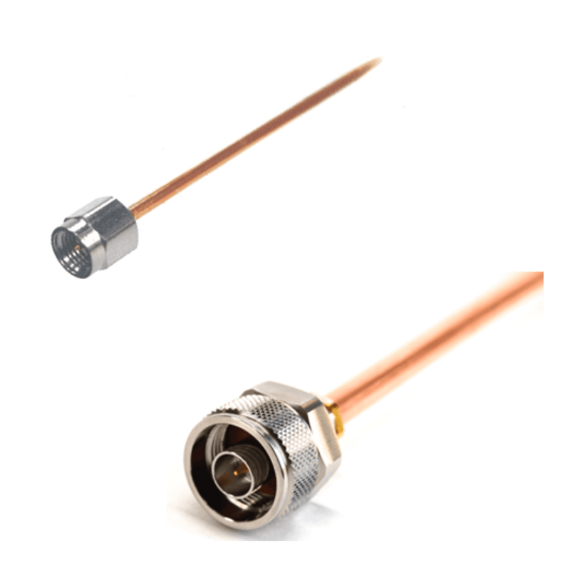
To complete signal transmission, connectors are attached to the cable ends, selected based on frequency band and impedance requirements.
What are RF Coaxial Connectors
A RF coaxial connector connects a coaxial cable to a device (electronic equipment). It is used in high-frequency applications. Its shape follows international standards, allowing compatibility between different manufacturers. The connector has male and female ends, called a plug (male) and a jack (female).

Basic Structure of a RF Coaxial Cable
A RF coaxial cable has a circular cross-section and typically consists of four layers from the center outward. If the characteristic impedance is not specified, it is referred to as "shielded wire" and may be distinguished from a "coaxial cable."
Four-Layer Structure of a Coaxial Cable
Inner Conductor: A central copper wire that carries electrical signals.
Insulator: A layer of insulation surrounding the inner conductor.
Outer Conductor: A braided or foil layer around the insulator. It acts as a ground during transmission and shields against signal leakage and external interference.
Outer Covering: Also called the jacket, this protective layer encases the cable’s exterior, often made of vinyl.

Trivia : Cable type
A seamless metal tube is desirable for the outer conductor, but it is difficult to bend. Braided copper wires have worse leakage characteristics than metal pipes, so there are cables that improve leakage characteristics by making braided copper wires into a double structure or wrapping aluminum foil or copper foil on the insulation.
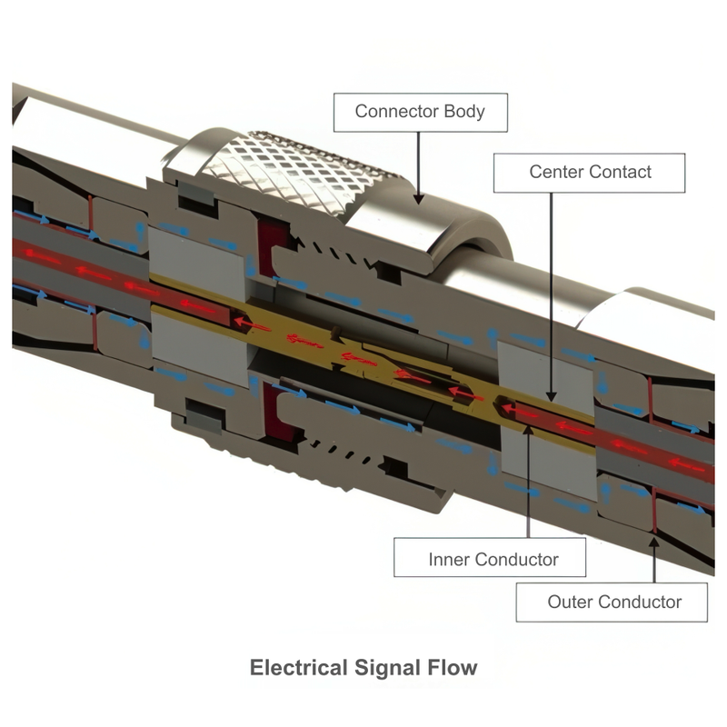
Electrical Signal Flow
Attaching a coaxial connector to a coaxial cable enables high-frequency signal transmission.
During installation, ensure the following connections:
・ The inner conductor of the coaxial cable contacts the center contact of the coaxial connector.
・ The outer conductor of the coaxial cable contacts the connector body.
RF Coaxial Cable Features
RF coaxial cables are designed to provide stable signal transmission with controlled impedance and low attenuation. They typically operate in frequency ranges from 1 MHz to 2 GHz, depending on the cable type.
Compared to shielded wires, they offer higher signal integrity, reduced electromagnetic interference, and consistent performance over long distances. They are also durable and relatively easy to install.
Minimum Bending Radius
RF coaxial cables are flexible but must not be bent beyond their minimum bend radius.
Excessive bending can degrade signal performance or damage the cable.
The minimum bend radius is typically about 10 times the cable’s outer diameter and is often denoted as R.
Applications of RF Coaxial Cables

- Broadcasting & TV: 75 Ω types like RG6 are standard for cable television (CATV) and satellite TV systems, ensuring signal quality.
- Wireless Comms: 50 Ω cables such as RG58 link radio transmitters and antennas for effective RF signal transfer.
- High-Speed Internet: Coaxial forms the backbone for networks delivering high-speed data.
- Medical Equipment: Essential in MRI machines for shielding sensitive equipment from RF signals.
RF Coaxial Cable Impedance Explained
RF coaxial cables are typically designed with characteristic impedances of 50 Ω or 75 Ω.
The impedance is determined by the ratio of the conductor diameters and the dielectric constant of the insulating material.
Selecting the correct impedance is essential for minimizing signal reflection and loss in RF systems.
50 Ω is commonly used for RF communication and testing, while 75 Ω is used for video and broadcasting applications.
Frequency Characteristics of RF Coaxial Cables
he usable frequency range of a RF coaxial cable depends on its diameter, dielectric material, and shielding quality.
Thicker cables and solid PTFE insulation allow operation at higher frequencies, while smaller, flexible cables are suitable for low- to mid-frequency applications.
Types of RF Coaxial Cables
RF coaxial cables come in different types based on their application. Below we will cover some common examples.

Trivia: RF Coaxial Cable Impedance
The impedance of a coaxial cable is like resistance to alternating current, with 50Ω and 75Ω being the most common types. 50Ω is mainly used for power transmission in wireless devices, while 75Ω is primarily for video and audio signal transmission in TV receivers. Under JIS standards, cables labeled with "D" indicate 50Ω (e.g., 3D-2V, 5D-2V), while "C" indicates 75Ω (e.g., 3C-2V, 5C-2V). The coaxial connector should match the cable's impedance to ensure proper performance.
These two impedance values became standard for the following reasons:
・ Early cables used air as an insulator, and the optimal conductor diameter ratio (outer conductor inner diameter / inner conductor outer diameter) for minimal loss was about 75Ω.
・ With polyethylene insulation becoming common, the optimal conductor diameter ratio shifted to about 50Ω.

Cable Name Example
RG-58A/U
- RG: Stands for Radio Guide (some sources suggest it also means Radio Frequency Coaxial Cable – General Purpose).
- 58: Model number (assigned sequentially upon standardization, not based on thickness like JIS standards).
- A: Denotes a standard revision (letters, such as A to C, indicate changes).
- U: Stands for Universal (general-purpose use).
We have a page with details on “Types, Standards, and List of Coaxial Cables”.
How to Choose RF Coaxial Cables
Choosing the right RF coaxial cable depends on several key factors:
- Impedance: Select 50 Ω for RF signal transmission (e.g., wireless communication) or 75 Ω for video and broadcasting applications.
- Frequency Range: Ensure the cable supports the required frequency range. Higher frequencies require cables with lower attenuation.
- Cable Type: Common types such as RG58, RG174, and RG6 differ in size, flexibility, and performance.
- Connector Compatibility: Match the cable with appropriate connectors such as BNC, SMA, or N-type.
- Installation Environment: Consider flexibility, bending radius, temperature, and exposure to outdoor conditions.
RF Coaxial Cable FAQs
QWhat are coaxial cables used for?
QWhat are coaxial cables used for?
Coaxial cables are primarily utilized for high-frequency signal transmission in a variety of applications, including telecommunications, television and radio broadcasting, internet services, military communications, and medical equipment. Their robust shielding against electromagnetic interference (EMI) ensures the integrity of signals, even over long distances.
QWhat is the difference between 50Ω and 75Ω coaxial cables?
QWhat is the difference between 50Ω and 75Ω coaxial cables?
- 50Ω coaxial cables are designed for radio frequency (RF) communications, wireless networks, and test equipment, offering minimal signal loss for power transmission.
- 75Ω coaxial cables are best suited for video and broadcasting systems, such as cable television and satellite connections, providing superior signal quality with minimal attenuation.
QCan I use a 50Ω coaxial cable for television?
QCan I use a 50Ω coaxial cable for television?
No, a 50Ω coaxial cable is not suitable for television applications. Television signals require 75Ω impedance for optimal performance. Using a 50Ω cable may lead to signal degradation and poor picture quality.
QWhat are the most common types of coaxial cables?
QWhat are the most common types of coaxial cables?
The most common types of coaxial cables include:
- RG Cables (Military Specification) – Commonly used in military and general RF applications. Examples include RG-6 for television and RG-58 for radio communications.
- JIS Standard Cables – Used in Japan's industrial applications. Examples include 3D-2V (50Ω) and 5C-2V (75Ω).
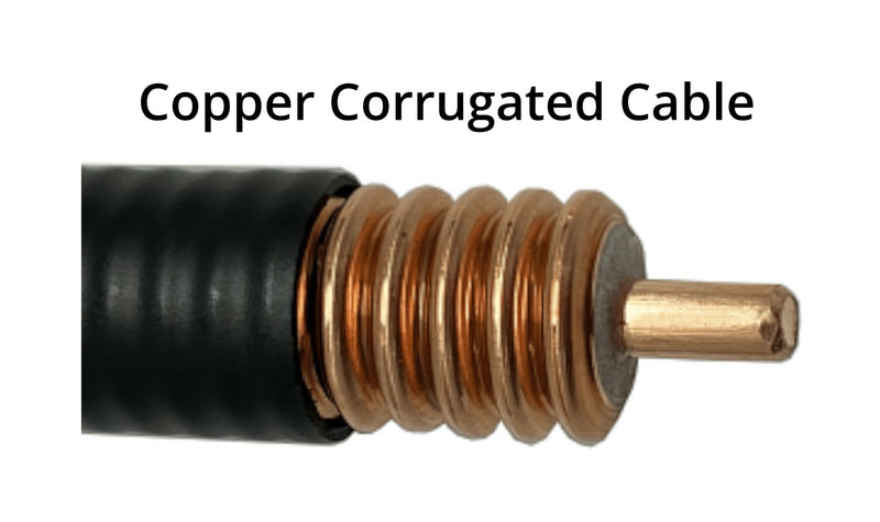
- Corrugated Copper Cables – Used in mobile base stations and wireless infrastructure.
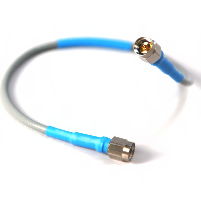
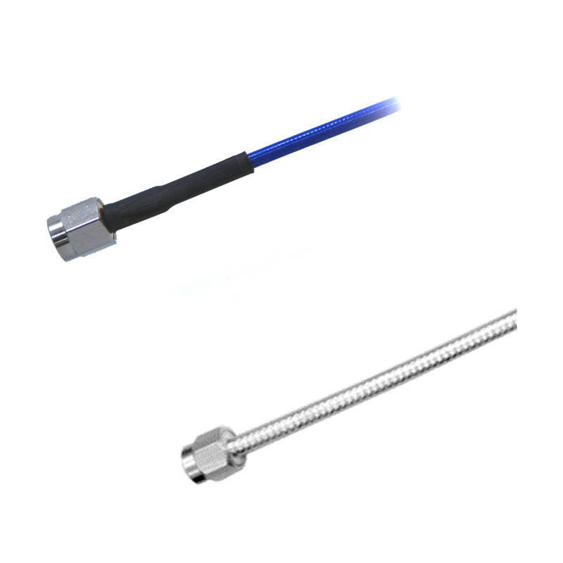
- High-Frequency Test Cables – Used in laboratory and precision measurement environments.
- Semi-Rigid and Semi-Flexible Cables – Suitable for aerospace and high-frequency applications.
QHow do I choose the right coaxial cable?
QHow do I choose the right coaxial cable?
When selecting the appropriate coaxial cable, consider the following factors:
- Impedance: Match the cable’s impedance (50Ω or 75Ω) with that of your device.
- Frequency Range: For high-frequency applications, choose cables designed to minimize loss.
- Flexibility: Flexible cables are ideal for installations requiring movement, while rigid cables are better suited for precision setups.
- Shielding: Select cables with appropriate shielding for environments with high interference.
QCan two coaxial cables be connected?
QCan two coaxial cables be connected?
Yes, two coaxial cables can be connected using coaxial adapters. However, each additional connection introduces the potential for signal loss, so it is advisable to limit the number of joins.
QHow can I minimize signal loss in coaxial cables?
QHow can I minimize signal loss in coaxial cables?
To minimize signal loss:
- Use high-quality cables with proper shielding.
- Keep cable runs as short as possible.
- Ensure proper impedance matching with low-loss connectors.
- Avoid sharp bends that exceed the minimum bending radius.
- For longer cable runs, consider the use of a signal amplifier or booster.
QWhat happens if a coaxial cable is bent excessively?
QWhat happens if a coaxial cable is bent excessively?
Excessive bending beyond the minimum bend radius can result in:
- Increased signal loss due to deformation of the dielectric insulator.
- Reduced shielding effectiveness, leading to electromagnetic interference (EMI).
- Permanent cable damage, affecting both performance and lifespan.
QCan I use coaxial cable for Ethernet?
QCan I use coaxial cable for Ethernet?
Modern Ethernet networks typically use twisted-pair cables (Cat5e, Cat6)or fiber optics, rather than coaxial cables. While earlier Ethernet standards (10BASE5, 10BASE2) used coaxial cables, today's home and office networks rely on Ethernet cables. However, coaxial cables continue to be used for broadband distribution by certain internet service providers.
QHow can I order coaxial connectors, and what support do you offer?
QHow can I order coaxial connectors, and what support do you offer?
Ordering is simple—you can purchase our coaxial connectors directly on our website or contact our sales team for assistance. We also provide full technical support, including datasheets, CAD models, and application notes, to help you pick the perfect connector for your project.
Purchase Guide
Tyclon coaxial connectors and processed coaxial cable products can be purchased directly online using a variety of credit cards.